
Honeynet Project
http://www.honeynet.org
Last Modified: 20 December, 2002
Honeynets can be difficult to configure and resource intensive to deploy,
requiring a variety of technologies and systems. Many users or organization that want
to research Honeynets may not have the resources for deployments. Therefore,
this paper will focus on building a Honeynet using a single computer and free,
OpenSource software. This will be accomplished by building a
Virtual Honeynet, using the OpenSource solutions User-Mode Linux (often called
UML) and IPTables. The format of this is paper is a HOWTO, it will describe
step by step how to build a Honeynet on a single computer and
then discuss one method of deploying Honeynet Data Control and Data Capture. This paper
assumes you have already read and understand the concepts in
KYE: Honeynets and the paper KYE: Virtual Honeynets.
This paper will not go into detail on
how to deploy advance Honeynet technologies. That will come later in the future
paper Know Your Enemy: GenII Honeynet. Instead, this paper will cover in detail
how to build a Honeynet testing environment using basic Honeynet technologies. If
this is the first time you have ever built or deployed a Honeynet, we HIGHLY
recommend that you first deploy this in a lab or test environment. You have been
warned.
Plan of Attack
Part I: User Mode Linux
Unlike VMware, UML does not require any additional virtualization software. Instead,
you patch the source of the Linux kernel you want to run as your Guest OS. This UML patch
converts the kernel into a executable binary called 'linux', which allows the Guest kernel
to run on your system as a seperate operating system. When you run this UML patched
kernel, all you need to do is give it a filesystem to use, and you now have a independent
Linux system running on your computer, two for the price of one! This new kernel is a
userspace application running on the real kernel (Host OS). The UML kernel receives system
calls from its applications and sends/requests them to the Host kernel. There are also
additional management and networking UML tools you can install on the computer that
makes your life easier.
Some of the most exciting features that have recently been added to UML are
designed specifically for honeypots. These capabilities signifigantly improve
our UML Honeynet. We will highlight three of these capabilities below, however
you can find the technical details and HOWTO at
http://user-mode-linux.sf.net/honeypots.html.
To build and install UML we will use a prebuilt rpm. RPM is a package manager
for Red Hat Linux, allowing us to simply install entire packages of software. The UML
package will do two things for us. First, it installs a prebuilt kernel with the
UML patch, this is installed as the executable binary 'linux'. This will allow us to run
a seperate Linux kernel. In addition, this package contains
all of the UML utilities. You can download all UML binaries and source code from the
UML Download Site.
Below is the command used to install a prebuilt UML rpm for a 2.4.19 kernel.
You can then see what files and utilities it installs.
host #rpm -ivh user_mode_linux-2.4.19.5um-0.i386.rpm
host #rpm -ql user_mode_linux-2.4.19.5um-0.i386
Thats it! By installing this RPM you have accomplished two things. First, you have installed the
executable kernel (/usr/bin/linux), this is our Guest kernel. Second, you have installed various
UML utilities. If you want to run any additional kernels at the same time, you only have to
download the prebuilt UML kernels, or use the UML patch on kernel source code. (** NOTE: Based on
our testing, it appears the RPM uml version 2.4.19-5 can only handle running one running kernel at
a time. If you want to run multiple kernels, you will have to download the latest UML kernel patch.)
Okay, there is only one step left for our Guest kernel, a file system. What good is having another
kernel when there is no file system for an attacker to interact with? Once again, we go to
the UML Download Site and find
pre-built filesystem images. Or if you prefer, you can simply build your own taking
a dd(1) image of an existing file system. For the purpose of this HOWTO, we install and use the
RedHat 7.2 server file
system image (65 MB in compressed size). We have modified this file system to include the binaries
telnet(1), vi(1), and pico(1). Once you have downloaded the image, you are ready
to go, no configuration involved. To start your new Guest operating system, you simply uncompress
the downloaded filesystem image, then startup your linux binary using the filesystem. The
command would look like:
host #gzip -d root_fs.rh-7.2-server.pristine.20021012.gz
When you execute the 'linux' command, you should see in your terminal a new
operating system booting up. You should hopefully end up with a login prompt. Just login
with the user 'root' and the password 'root' giving you access to the operating system. Congrats,
you did it! Now, lets explain what you just did, and where to go from here.
Part II: Setting up the Network
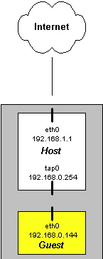
The eth0 part of the command creates
the interface eth0 on the Guest OS, telling it the interface logically routes through
tap0 on the Host system. The only thing we have left is to give the eth0 on our Guest OS
an IP address on interface eth0. This is already done on our pre-built file systems.
In the case of our pre-built RedHat 7.2 server, its IP address on eth0 is 192.168.0.144.
If you want to change any of the configurations on the Guest RedHat server, you simply
make those modifications like you would on any other system. To confirm this setup,
run on the Guest OS the commands:
guest #ifconfig -a
For a better idea of what your virtual network now looks like,
refer to Figure 2.
The next step is to confirm that the Guest system can talk to and route through the gateway.
This means you want to first ping the IP address of the default gateway, in this case 192.168.0.254.
This is in reality interface tap0 on the Host system. Once you confirm that you can ping
the internal interface, attempt to ping the external interface of Host system (most likely
the IP address bound to eth0). This ensure that you are also routing through the Host system.
If ping did not work, ensure you are not running a firewall on the
Host, and double check your network setting on the Host and Guest operating system. To confirm
this setup, on the Guest OS run the commands:
Part III: Data Control
The first thing you have to decide is if
you want your gateway to run in layer three routing mode,
or layer two bridging mode. Layer two bridging (also known as GenII, or 2nd
generation) is the prefered method. When your gateway is acting as a bridge, there
is no routing or TTL decrement of packets, it acts as an invisible filtering device,
making it much more difficult for attackers to detect. However, for IPTables to
work in bridging mode, your kernel must be patched to support it. By default, most
kernels do not support IPTables in bridging mode. Red Hat kernel 2.4.18-3
is one of the few that does support this by default. If you want to patch your kernel to support
this, you can find the patch at
http://bridge.sourceforge.net/download.html. For the purpose of this howto, we will
assume your Kernel does NOT support IPTables in bridging mode. So we will describe how
to build your virtual Honeynet with your gateway in routing mode using Network Address
Translation.
Lets cover how to configure the rc.firewall
script to implement this functionality. There are two critical areas to
configure, the networking issues and control issues. For networking, we have to identify
the IP addresses and the networks of the Host and Guest systems. If you are running in
layer three routing mode, the script takes care of all Network Address Translation
issues. If you are running in layer two bridging mode, the script takes care
of all bridging issues. Remember, for the purpose of this paper we are using layer
three routing. For control, we have to define how many outbound connections we allow
from the Guest systems. There will be at least five variables that will be different
on your system, and you will have to modify. Specifically,
First, by default the rc.firewall script
runs in layer two bridging mode. You will have to modify it to run in layer
three routing mode.
Second, you will need to set the public IP address of the Guest OS.
This is the external IP address you use for Network Address Translation.
This is also the IP address hackers will use to attack your virtual
honeypot. If you are using your gateway in bridging mode,
this variable will also be used, however you give it the real IP's
of the honeypots, as there is no address translation.
PUBLIC_IP="192.168.1.144"
Third, you will need to configure the internal IP address of the
honeypot. This is the real IP address of your Guest OS. This
variable is not used if you are in bridging mode.
Fourth, you will need to configure the external IP address of the
Host OS. This is the external IP address of your firewall, your
gateway. For our example, we use the following.
Last, you will need to identify the name of the internal interface
of the Host OS. By default, this is eth1. However, we are using
the virtual interface tap0, and have to modify this variable.
These are the minimum varaibles you have to modify, there may be others
depending on the configuration of your system. There are other
options you can update, such as remote management, limiting
what connections the firewall can initiate, and giving your honepyots
unrestricted DNS access. Also, by default, the script limits each honeypot the
following outbound connections per hour; 9 TCP connections, 20 UDP connections,
50 ICMP connections, and 10 IP other. Details of the script are beyond the
scope of this paper. To better understand these variables, we recommend
you review the script in detail and try out the different options
in a lab environment. Once you have configured the
rc.firewall script, you implement
it by executing the script.
host #/.rc.firewall
To confirm you have successfully ran the script, there are two thing you want to check.
First, ensure that address translation is working. You can confirm this if a new, logical
interface has been added to the Host system. Second, review the IPTables rules.
Once confirmed, your Data Control is in place.
There are also a variety of other tools for implementing Data Control. For example, you
can incorporate the use of Snort-Inline to block or modify known attacks. This is done by
taking advantage of the QUEUE option in the IPTable scripts. Other options include use of
bandwidth throttling. However, these advance capabilities are beyond the scope of this
paper. For additional options, check out
Honeynet Tools Section.
Part IV: Data Capture
For IPTables, the logging has already been configured for us with the rc.firewall script.
It is configured to log all new inbound and outbound connection to /var/log/messages. Any inbound
connection is an indication of a probe, scan, or attack. Any outbound connection indicates that
a honeypot has been compromised. The value of IPTable logs is one primarily for alerting. The
logs do not have enough information to tell us what the attacker is doing. For
Snort, we configure it to capture every packet and its full
payload that enters or leaves the Honeynet. Linked here is a
Snort config file that will capture and log attacker activity..
You will find a simple Snort startup script
that starts Snort and uses the recommended Snort config file. Be sure to update
the startup script to monitor the tap0 interface of the Host OS. You will most
likey want to run this script daily, running the script from cron.
host #./snort-start.sh
There are also a variety of other tools for implementing Data Capture which are beyond
the scope of this paper, such as Sebek. For additional options, check out
Honeynet Tools Section.
Part V: Testing Your UML Honeynet
First we open a terminal on the Host OS and monitor the IPTable logs in
/var/log/messages. When we initiate outbound connections from the Guest OS
through our Host gateway, we should see the attempts logged there. This information
is critical for alerting purposes,
indicating the honeypot has been hacked, and the attacker (or automated tool)
is attempting outbound connections. Starting with the 10th outbound
attempt, the TCP connections should be blocked (the limit was met)
and logged. Below is the command you want to execute before attempting
any outbound connection.
host #tail -f /var/log/messages
Next, open a terminal on the honeypot system, our Guest OS.
From there you will initiate a variety of outbound TCP connections.
For example, from the Guest OS attempt to Telnet to a different systems
on the external 192.168.1.0/24 network. It does not matter if these systems
exist or not, just as long as the initial connection is attempted. The
packets should be routed through the tap0 interface on our Host OS system and logged
by the IPTables firewall in /var/log/messages. We should see nine connections
allowed outbound, then anymore after that dropped. All these attempts
should be logged.
Guest #telnet 192.168.1.105
Guest #telnet 192.168.1.220 21
Guest #telnet 192.168.1.5 80
Guest #telnet 192.168.1.115 6667
If you see the attempts logged, and blocked after the limit. You have
successfully implemented Data Control.
Next, we want to ensure that Data Capture is happening, specifically that
the Snort process is capturing all packets and their full payload that
are entering and leaving the Honeynet. A Snort process should be monitoring
the internal interface of the Host OS, specifically tap0. To test this,
attempt to ping several systems on the 192.168.1.0/24 network.
Guest #ping -c 3 192.168.1.105
The Snort process should have captured the three ICMP Echo Request packets and
their full payload. It should have logged the activity to tcpdump binary log
format. To confirm, review the log file, an example is below.
Thats it! You have just completed a very basic test of your Data Control and
Data Capture capabilities. There are far more advance tests you can attempt,
such as using a second, seperate computer to act as a system on the
Internet and interact with the honeypot. However that is beyond the scope of
this paper.
Conclusion
This paper is broken down into five parts. In the first part we will describe what UML is,
how it works, and how to install and configure it. In the second part, we describe
how to create a network of multiple systems on your single computer, including all
network issues. In the third part we describe how to implement Data Control on your
UML Honeynet using IPTables. In the fourth part we describe how to implement
Data Capture using Snort. Finally, in the fifth part, we describe how to test your setup.
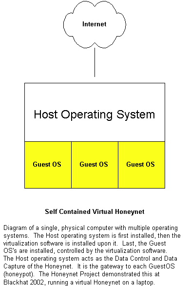
User-Mode Linux is an OpenSource solution that creates a virtual Machine.
Created and maintained by Jeff Dike, you can find it at
http://user-mode-linux.sourceforge.net.
UML allows you to run multiple instances of Linux
on the same system at the same time. This capability is similar to the
commercial solution VMware,
however UML is currently limited to Linux. UML is designed for a variety of
purposes, such as kernel debugging, testing applications, etc. We are going to use this
capability to run a Honeynet on a single computer, specifically a single gateway with one
honeypot behind it. For this purpose of this paper, we will explain how to install and run
UML on a Red Hat 7.3 system. We will use the same terminology used in VMware software, specifically
the Host system is the original operating system running on the box. Any and all additional
operating systems added (the virtual operating systems) will be called Guest systems.
To visualize this deployment, refer to Figure 1
in the KYE: Virtual Honeynets paper.
/usr/bin/jailtest
/usr/bin/linux <- executable binary that is really the UML kernel, the Guest OS
/usr/bin/tunctl
/usr/bin/uml_mconsole
/usr/bin/uml_moo
/usr/bin/uml_net
/usr/bin/uml_switch
/usr/lib/uml/config
/usr/lib/uml/modules-2.2.tar
/usr/lib/uml/modules-2.4.tar
/usr/lib/uml/port-helper
host #linux ubd0=root_fs.rh-7.2-server.pristine.20021012 eth0=tuntap,,,192.168.0.254
Okay, now that you are running two operating systems, the next step is to get the Guest
OS, our honeypot, to route through our gateway and out to the Internet. This means, if
anyone wants to talk to our Guest OS, they first have to go through the Host. You may
not realize it, but you have already setup all the issues involved. Refer to the last
command above we executed, where we launched the command 'linux', specifically the
part eth0=tuntap,,,192.168.0.254. This command does two things. First, it creates
a new logical interface on the Host system called tap0. This logical interface is now
the gateway interface for the Guest OS, our honeypot. The IP address of the tap0 interface, and the
default gateway of the Guest OS, is 192.168.0.254. The only thing that will be different
for you is the IP address of eth0 on your Host system, this will vary depending on whatever you
configured it as. In the case of our example, it will be 192.168.1.1. To confirm your setup,
on the Host OS run the command:
guest #netstat -nr
Once you have setup the UML and networking, the next step is Data Control. The purpose of
Data Control is to contain what the attacker can do inbound and outbound of the Honeynet.
Typically, we allow anything inbound to the Honeynet systems, but limit outbound connections.
For the purpose of this paper, we will use IPTables, an OpenSource firewall solution that
comes with Linux. IPTables is a highly flexible stateful firewall, including the ability
for connection limiting, network address translation, logging, and many other features.
We will configure IPTables to act as a filter on our Host,
counting outbound packets. Once a limit has been met for outbound connections,
all further attempts are blocked, preventing the compromised honeypot from harming
other systems. Configuring and implementing these capabilities can be extremely
complex. However, the Honeynet Project has develop an IPTables script called
rc.firewall that does
all the work for you. You merely have to modify the script variables as they apply
to your Honeynet, then run the script.
# The MODE variable tells the script to #setup a bridge HoneyWall
# or a NATing HoneyWall.
MODE="nat"
#MODE="bridge"
HPOT_IP="192.168.0.144"
INET_IP="192.168.1.1"
LAN_IFACE="tap0"
Once we have completed Data Control, the next step is Data Capture. The purpose of
Data Capture is to capture all of the attacker's activity, without them knowing. There
are a variety of methods to implement this, however we will focus on two, IPTable logs
and Snort. IPTable logs are the logs generated by the firewall whenever there is an inbound
or outbound connection. Snort is an OpenSource IDS
solution which we will use to capture all network activity. As we discussed earlier,
UML also has the capabilities to capture all TTY activity from kernel space.
The fifth, and final step, of building our UML Honeynet is to test our configuration,
specifically Data Control and Data Capture. We want to ensure that our Honeynet
requirements are behaving as expected. Testing Data Control is relatively simple.
We want to ensure that any attempt by the honeypot to initiate an outbound connection
is both logged and controlled. By logged, all connection attempts should log an entry
to /var/log/messages, alerting us that an outbound connection has been initiated, and
the honeypot has most likely been compromised. Also, once the limit has been met, we want to ensure
that no more outbound connection are allowed. For the purposes of this paper,
we will test outbound TCP connections, which by default are limited to 9
attempts per hour. To test this we will need two terminal windows open.
Trying 192.168.1.105...
Trying 192.168.1.220...
Trying 192.168.1.5...
Trying 192.168.1.115...
The purpose of this paper was to describe step by step how to build a virtual
Honeynet using OpenSource tools. The value of this solution is an easy and
cost effective Honeynet for research and development. It is hoped that this
paper will make it easier for the security community to work with and understand
Honeynet technologies.